


Nickel Hydraulic Soft Close Drop In Cup Cabinet Hinge F910H
F910H Nickel Hydraulic Soft Close Drop In Cup Cabinet Hinge In Six Photographed Positions

This listing is written from the six photographs on this page, and what they show is a cup cabinet hinge in bright nickel: the front view with the hinge standing upright and the dark damper section visible on the body, the side profile with the alloy tail and its adjustment slot across the frame, the open side view with the cup worked out, the open edge view with the knuckle and the damper section facing the camera, the two-piece arrangement with the mounting plate shown separated beside the hinge, and one hinge on a bench scale whose display reads 98.4. The model is designated by the folder as a hydraulic, soft close, drop in cup hinge with an alloy tail, and the 35 millimetre cup is the drawing specification, so this page carries each of those points and is honest about which of them the photographs prove.
Two positions are stated plainly rather than implied. First, the dark section on the body is visible in the front, open and edge views, and that is the damper position on a hydraulic hinge of this class, but what a photograph proves is the part being there, not the closing feeling, so the soft close behaviour is confirmed from the drawing and felt on a sample before the production order is cut. Second, the 35 millimetre cup size is the model specification from the drawing, not a measurement taken from these photographs, and the specification table says so. The alloy tail is the folder designation for the tail part, shown in the profile frame as the bright finished arm of the hinge.
The Damper Section The Photographs Can See
A soft close cup hinge of this class carries its closing mechanism as a distinct section on the body, and that is what the staged frames show: the dark section at the base of the body in the upright front view, the same dark part facing the camera in the open edge view, and the dark cup interior in the open side view. The dark section is the damper on this hinge, the part that takes the door's energy in the last degrees of the swing so the door comes to rest against the case instead of striking it, and the photographs put that part in view rather than hiding it, which is the difference between a damper that is drawn on the drawing and one that is in the hinge you are looking at.
What the photographs do not prove is the closing feel. A hinge can carry the damper section and still close hard if the case is built wrong, the door is heavy for the hinge, or the hinge is fixed crooked, so the soft close behaviour is confirmed two ways before an order: the drawing states the closing class, and the sample is worked through its full swing in the buyer's own board, where the last degrees of the swing are what a buyer actually buys. The damper section is visible in the frames; the closing is something the sample proves.
The Drop In Mount, Shown In Two Pieces

One of the staged frames is the two-piece shot: the complete hinge standing, and the mounting plate shown separated beside it. That is the drop in arrangement, and the frame shows the two parts a fitter actually handles. The plate is fixed to the case face first, and the hinge then drops onto the plate with the cup in its recess, so the fixing screws and the hinge screws are separate operations rather than one crowded job. A drop in hinge is bought for the fitting speed: the plate goes on before the door is in position, the door is hung, and the hinge is dropped and screwed, with no measuring through a closed gap.
The separated plate in the frame is the part to check against the case construction, because the plate carries the case fixing holes and the hinge carries the door side fixing, and the two halves of a drop in hinge are specified together. Which plate an order ships with is fixed on the order, and the drawing lists the plate and its hole centres so the case and the hinge agree before the cutting is done.
What The Photographs In This Listing Prove
Every structural claim on this page can be pointed at in one of the six frames: the cup, the knuckle, the dark damper section on the body, the T-wing mounting plate and its fixing holes, the alloy tail with its adjustment slot in the profile view, the two-piece drop in arrangement with the plate separated, and the bench scale reading 98.4 for one hinge. What no photograph on this page proves is the 35 millimetre cup bore, the overlay, the door load limit or the cycle count, so none of those figures is carried as a photograph fact. They come from the hinge drawing and the test report, and a figure borrowed from a similar hinge is the most expensive kind of typo in a workshop, so they are issued against this model rather than assumed.
The staged set also omits, on purpose, the remaining photographs of this folder that repeat the same positions at slightly different angles. What remains is six different views of the hinge, and each of the six is used once in the image gallery on this page.
How The Hinge Is Built

The profile frame is the clearest way to read a hinge of this kind: the cup at one end, the alloy tail running out to the knuckle, the body between them, and the T-wing plate where the case fixing sits. Three things about this construction are worth a buyer knowing before the drawing arrives. First, the tail is the bright finished arm of the hinge, designated as the alloy tail by the folder, and it carries the adjustment slot that lets a fitter trim the door gap after the hinge is fixed, which is the reason a cabinet hinge of this class is sold with an adjustable tail rather than a fixed one. Second, the T-wing plate is a flat stamped part with its fixing holes spread across the wings, and the spread is what holds a door flat while it is working through the swing. Third, the dark damper section sits on the body where the front and open views show it, and the cup is the part that drops into its recess in the door.
- Cup in bright nickel, the part that drops into its recess in the door.
- Dark damper section visible on the body in the front, open and edge views.
- Alloy tail with its adjustment slot, shown across the profile frame.
- T-wing flat mounting plate carrying the case fixing holes.
- Knuckle at the joint where the body pivots on the tail.
- Two-piece drop in arrangement shown with the plate separated beside the hinge.
- One hinge on a bench scale, the display reading 98.4.
The Alloy Tail And Its Adjustment Slot
The tail of a cabinet hinge does three jobs at once: it carries the door side of the swing, it sets how far the door edge stands off the case, and it is the part a fitter adjusts when the gap is wrong. The folder designation for this tail is the alloy tail, and the profile frame shows it as the bright finished arm of the hinge with the adjustment slot in it. The slot is what makes the hinge serviceable: a screw on the tail reaches through the slot and moves the door edge a few millimetres in or out, so a door that was hung true can be brought back true after a season of board movement, and a gap that was slightly wrong at fitting time can be corrected without taking the hinge off the case.
The material of the tail is the folder and drawing designation rather than something a photograph can certify, and that is stated here rather than implied. What the photographs do show is the tail as one bright finished piece with the rest of the hinge, the slot in its centre line, and the fixing holes at its end. The drawing names the tail material and the slot travel, and those are the two figures a buyer should hold the sample against, because a tail that does not adjust through its full slot is a hinge that cannot be set on a case that has moved, and that is the failure a fitter blames first.
The Cup And The 35 Figure
The cup is the part of a cabinet hinge that the door is bored for, and the 35 millimetre figure on this model is the cup bore from the drawing. The staged frames show the cup in the front view at the top of the upright hinge, in the open side view worked out of the body, and in the two-piece frame where the cup sits above its plate position, but the diameter itself is not a photograph measurement. A boring jig set to the drawing figure is what cuts the recess, and the hinge is then dropped in against it, so the drawing number, not the photograph, is the number the workshop works from, and this page says so because a hinge ordered against the wrong cup bore is a door that never hangs true.
The overlay is the companion figure: how far the closed door stands over the case, and it is set by the tail and the plate together, which is why the drawing carries the overlay for this plate and the case geometry has to allow it. The adjustment slot on the tail covers the small end of the tolerance, the door edge moving a few millimetres, while the overlay figure covers the design intent, and both come from the drawing rather than from any figure on this page.
How Many Hinges A Door Needs
Hinge count follows door height and door mass, not preference. A tall door hung on two hinges works the upper fixing into a groove over a season, and the first symptom is never the hinge: it is the screw holes. On a wardrobe or cabinet door of this class the practical rule we work to is two hinges up to a modest height, three above that, and an extra hinge at mid height on a tall or heavy door so the middle of the rail is not carrying the twist. The break points depend on the door and the board, so they are agreed against the drawing rather than assumed on a page, and the bench scale frame with its 98.4 reading is the per-piece weight the carton maths runs from.
A soft close door is one case where the count argument leans up rather than down: the damped closing loads the fixings through the last few degrees of every swing, which a free swinging door does not do, and a tall door that could manage two standard hinges often wants three of a hydraulic hinge, with the mid fixing holding the line while the closing runs. On a drop in hinge the count also changes the fitting sequence, because each plate is fixed before its hinge is dropped, and a three hinge door means three plate positions laid out on the case before any door is lifted.
Where This Hinge Is The Right Call, And Where It Is Not
A nickel finished hydraulic soft close drop in cup hinge with a T-wing plate and an alloy tail belongs inside furniture that needs the door to close gently and the fitting to stay simple: wardrobe doors, tall cabinet doors, kitchen doors where a striking door is out of the question, bedroom furniture, office casework, and any casework where the door weight and the swing have to be carried by a hinge that a fitter can set in an afternoon. With the door closed the hinge sits inside the rail and the cup recess, and nothing shows but the door line. It is the wrong call for a marine locker, a hosing down area, a food processing room or an unventilated external cabinet in a coastal position: the finish is a decorative interior finish rather than a marine barrier, and bright plating always has pinholes at the knuckle where salt and chlorine start. For wet or coastal work we quote a stainless hinge instead, even though it costs more per fitting, because a hinge that corrodes through in one season costs more than the hinge ever did.
How This Hinge Sits In Our Range
Within our own hinge range, a buyer choosing a cup hinge is usually choosing between the closing, the mounting and the tail, in that order. The closing sets how the door comes to rest; the mounting sets how the hinge meets the case; and the tail sets how the door gap is held after the case has moved. This hinge is specified by all three: the hydraulic soft close closing with the damper section visible on the body, the drop in mounting with the plate shown separated, and the alloy tail with its adjustment slot. A buyer comparing it against our standard opening cup hinges should compare the same three, because the difference is the closing behaviour and the mounting, and both are things a white background photograph shows only partly.
It also sits against the heavier duty hinges we supply for doors that carry more mass than a soft close hinge of this class should, and the honest position is the one on the specification table: the cup bore is the drawing figure, the closing is the model designation, and the tail material is the folder designation, each confirmed on the drawing and the sample rather than read off the frames. A buyer who needs the soft close on a heavier door, or the drop in mounting without the damping, should say so on the order, because the family is built around those choices and the drawing is what ties the choice to the part number.
Specification Summary
| Model | F910H |
| Hinge type | Hydraulic soft close drop in cup cabinet hinge, 35 cup class, for wardrobe and cabinet doors |
| Cup | 35 millimetre cup bore as the model specification from the drawing, not measured from the photographs |
| Closing | Hydraulic, soft close; the dark damper section is visible on the body in the staged frames and the closing behaviour is confirmed from the drawing and the sample |
| Mounting | Drop in: the mounting plate is fixed to the case and the hinge drops onto it, shown as the two pieces in one staged frame |
| Tail | Alloy tail as the folder and drawing designation, with its adjustment slot shown in the profile frame |
| Mounting plate | Flat stamped T-wing plate carrying the case fixing holes |
| Body | Cup hinge body in bright nickel across the whole assembly |
| Per piece weight | Bench scale in the staged frame reads 98.4 for one hinge |
| Finish | Bright nickel |
| Door material | Panel materials that can be bored to the drawing: chipboard, MDF, plywood, solid timber rails |
| Overlay, door load and cycle count | From the hinge drawing; not read from photographs |
| Fixing screws | Not supplied as standard unless agreed on the order |
| Sample policy | Samples before a production order so the hinge can be fixed and hung in the buyer's own board and the closing felt through the full swing |
How Each Hinge Batch Is Checked Before Packing
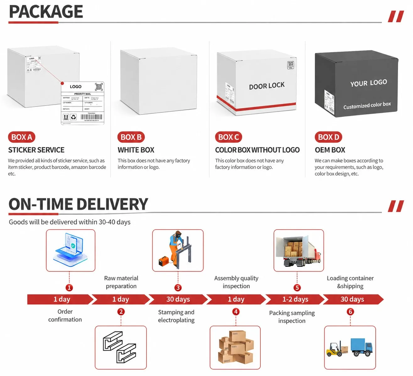
Every hinge batch is sampled on four points before packing. Assembly: the cup, the tail, the plate and the damper section are checked to be present and seated, the knuckle is checked to sit square rather than cross loaded, and the tail screw is checked to run through its slot with the full travel rather than binding at one end. Appearance: the nickel surface is checked for passivation marks, handling scratches and any plating that has pulled at the knuckle radius, which is the part of the hinge that shows first in a lit wardrobe. Function: each sampled hinge is worked through its full swing by hand, opened and closed, so a binding joint or a closing that strikes instead of damping shows up before the carton closes, and the drop in engagement is checked by dropping the hinge onto its plate and confirming it seats flat. Packing: carton quantity, inner bag, marking and the model number on the label are checked against the order rather than the previous job, and the documents a buyer needs at their own customs are issued with the proforma.
Who Supplies This Hinge
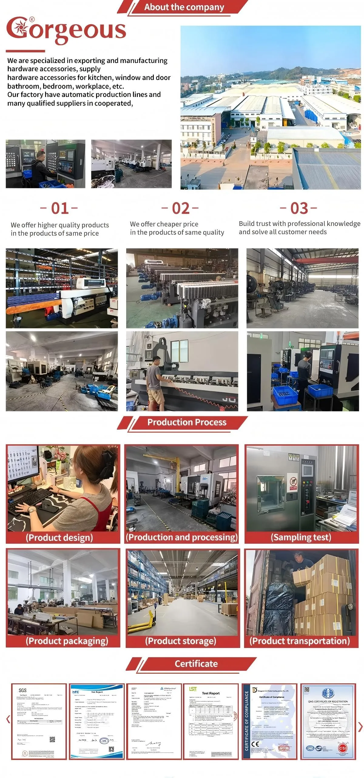
This hinge is supplied by Guangzhou Gorgeous Intelligent Technology Co., Ltd., a furniture and architectural hardware business whose range covers hinges, drawer slides, handles, stays, legs, castors, locks and the fitting sets that go with them. The company works to export orders: quantities, carton marking, barcodes and shipping documents are agreed before production rather than after it, and a buyer who specifies the plate, the tail and the screw type on the order gets those things made, because that is the only specification the factory works from.



Terms Worth Agreeing Before Two Hinges Are Compared
- Soft close cup hinge: a cup hinge whose closing is damped by the damper section on the body so the door comes to rest against the case; the dark damper section is visible in the staged frames and the closing behaviour is confirmed from the drawing and the sample.
- Hydraulic drop in hinge: a hinge that closes on a damped path and mounts by dropping onto its plate; the drop in arrangement is shown as the two pieces in one staged frame, and the damping is the model designation.
- Alloy tail cabinet hinge: a cabinet hinge whose tail is the alloy part designated by the folder, shown in the profile frame with its adjustment slot; the tail material is the drawing figure rather than a photograph fact.
- 35 cup: the cup bore as the model specification from the drawing; the frames show the cup in three positions, and the boring jig is set to the drawing figure rather than to a photograph.
- 35mm cup hinge: the trade term for the cup bore class of this hinge, the 35 millimetre figure carried on the drawing; the frames show the cup in three positions and the jig is set to the figure, not to the photograph.
- Clip on hinge: the mounting arrangement shown in the two piece frame, where the hinge drops and clips onto its plate instead of being screwed on through the case face; the drop in mounting of this hinge is the clip on mounting of the trade.
- Plate: the half of the hinge fixed to the case; the T-wing plate and its holes are part of the hinge specification, and the two-piece frame shows the plate separated from the hinge.
- Overlay: how far a closed door sits over the case; the drawing shows it for this plate and tail, and the case geometry has to allow it.
- Adjustment slot: the slot in the tail that takes the tail screw and lets the door edge be trimmed after fitting; the full slot travel is what the sample is checked against.
- Fixing holes: the holes that carry the case screws on the plate and the door screws on the hinge; the pilot hole and screw gauge are part of the holding, not just the hinge.
- Drawing: the document that turns a hinge photograph into a hinge specification; without it the cup bore and the overlay cannot be checked, and we send it with the quotation.
Common Hinge Faults And What They Actually Mean
A door that drops over time is almost always a fixing problem rather than a hinge problem. The hinge is the strongest part of that joint; the board it is screwed into is not. In chipboard and MDF the holding power depends on the pilot hole and the screw gauge, and a plate that has been screwed and unscrewed repeatedly while a fitter chases the line loses grip, which shows up later as the plate pulling away from the carcass while the hinge itself is still sound. On a drop in hinge the symptom can look like the hinge working loose on its plate, because the hinge carries the door load through that one engagement, and the answer is still the plate fixing, not a heavier hinge.
A door that will not square up is usually a tail and slot question: the tail screw sets the door edge, and a slot that is at the end of its travel means the hinge is being asked to correct a gap the case does not have, which is a case geometry problem wearing a hinge costume. The answer is checking the case edge against the drawing and the sample, not forcing the door or swapping the hinge for one nobody has specified. On a hydraulic hinge a closing that feels hard or uneven at the last degrees is an alignment or a door load question, and both are fixed at the bench with the sample door, which is why the sample comes first on a new case: the buyer feels the closing in their own board before the production order is cut.
The faults that actually do come from the hinge are the cup, the plate and the tail: a cup that does not seat in its recess because the boring is wrong for it, a plate that was fixed crooked, a tail that was bent during fitting, and screws that were driven over the top instead of home. None of those is a hinge defect, but they all show up as one, and the way to keep a soft close drop in hinge working is the same as the way to keep any hinge working, which is to fix it true the first time with the right screws in the right holes.
Questions Buyers Ask About This Hinge
- Is F910H a soft close hinge? Yes: the F910H is designated the hydraulic, soft close, cup hinge, and the dark damper section is visible on the body in the front, open and edge staged frames. The photograph proves the part is in the hinge; the closing feel is confirmed from the drawing and demonstrated on a sample in your own board, and we will confirm it in writing before you order.
- Is the cup 35 millimetres? 35 millimetres is the model specification on the drawing for this hinge, and it is stated as such on this page rather than as something the photographs measure. The frames show the cup in three positions, and the boring jig is set to the drawing figure against your door material before you cut anything.
- What is the alloy tail? The tail of the hinge, the part that carries the door side of the swing and the adjustment slot, designated as alloy by the folder and the drawing. The profile frame shows the tail as the bright finished arm of the hinge with the slot in its centre line, and the drawing names the material and the slot travel.
- How does the drop in mounting work? The T-wing plate is fixed to the case face first, the door is hung with its cup recess bored to the drawing, and the hinge drops onto the plate with the cup seating in its recess. One staged frame shows the two pieces separated, which is the arrangement a fitter actually handles, and the drop in engagement is checked on the sample before the order.
- How many do I need on a tall door? Two up to a modest door height, three above it, and an extra hinge at mid height on a tall or heavy door, because the damped closing loads the fixings through the last degrees of every swing and the mid fixing is what keeps a tall door flat.
- What is the finish and is it wet area rated? A bright nickel finish, the same colour on cup, body, tail and plate. It is an interior finish; for wet, hosed or coastal applications we quote a stainless hinge instead.
- Are the fixing screws included? Fixing screws are not supplied as standard unless agreed on the order; the drawing lists the specification we would ship so the screws match the holes in the plate and the hinge.
Sign-Off Checklist Before You Order This Hinge
- Door material confirmed as a panel material that can be bored to the drawing for this hinge.
- Cup recess bored to the drawing figure of 35 millimetres, not to a photograph, with the depth checked for the drop in seating.
- Door height and mass confirmed against the hinge count, with an added hinge at mid height on tall doors.
- Hydraulic closing requirement confirmed in writing against the drawing, and felt on a sample in the buyer's own board, since the closing behaviour is the point of buying the soft close hinge.
- Plate confirmed against the case construction and the fixing method, with the wing holes on the drawing centres.
- Overlay requirement confirmed so the closed door sits at the drawing position over the case, within the tail slot travel.
- Screw specification agreed separately, since fixings are not supplied as standard.
- Environment confirmed as dry or moderately humid; wet, hosed and coastal work is outside this finish.
- Sample worked through the full swing in the buyer's own board before the production order is cut, closing felt through the last degrees.
Ordering
Send the model number F910H with the quantity, the destination port and the carton marking you need. Samples are available before a production order so the hinge can be fixed and hung in your own board, the closing felt through the full swing, which is the fastest way for both sides to agree that the drop in seating, the tail adjustment and the soft close closing are right. The drawing, the fixing sheet and whatever test documentation we hold for this hinge model are issued on request, and delivery and payment terms are agreed order by order on the proforma rather than assumed from a previous order.


Comprehensive score