


90 Degree Panel Connector Zinc and Plastic K424
The K424 Panel Connector In Twenty-Eight Frames
The K424 is a small part that does a structural job: it holds two panels at a right angle. The shape is consistent across every frame in this folder - an upright face with a wing at each top corner and a fixing hole in each wing, a foot plate standing square to that face, a gusset filling the corner between the two, and a single screw in the middle of the upright. The wing shape is not decoration. It puts the two fixing holes as far apart as the panel width allows, which is what stops the connector rotating once it is loaded.

Three versions appear side by side in the frames and they are the same part in three materials. The first is die-cast zinc, plated, with the gusset visible as a cast triangle inside the angle. The second is moulded clear, which is why the ribs and the boss behind the screw can be seen through it. The third is moulded ivory, opaque, and reads as the neatest of the three in a light-coloured carcass. K424 covers the metal version and K4241 covers the moulded one; the drawing and the panel thickness decide which is right for a given joint, not the colour on the shelf.
What The Three Materials Are For
The die-cast version is the one for a joint that has to carry load or be taken apart more than once. Metal holds its shape when a screw is driven hard, it does not creep under a sustained pull, and it survives being over-tightened by somebody who does not trust a screwdriver. The moulded versions are lighter and cheaper, they will not mark a finished face, and they are the sensible choice where the connector is inside a carcass that will never be opened. In a clear moulding there is a further advantage: the joint can be inspected without dismantling it, because the screw and the boss are visible through the body.
What the mouldings will not do is take the same torque as the metal. A moulded connector driven hard will crack at the boss or spread at the wings, and once it has spread it will not hold the angle. That is why the same shape is offered in three materials rather than one: the form is settled, and the material is the variable the buyer actually chooses. Ask for the torque the boss will take if the joint is going into something that gets handled, and match it to the driver on the line.

The Gusset Is The Point
Look inside the angle on any of the frames and there is a triangular web joining the upright face to the foot plate. On the zinc version it is cast; on the mouldings it is a pair of ribs doing the same work. Without it, this connector would be two flat plates meeting at an edge, and the angle would open the moment the joint was loaded across it. The gusset turns the corner into a section that has depth, and the connector stops flexing.
That is also why the connector suits a joint that only has one accessible face. The foot plate is fixed down to the panel the fitter can reach, and the upright face is fixed into the second panel from the side. A flat plate bracket needs both faces clear to drive its screws; this connector needs one face and a screwdriver angled at the other. In a carcass assembled from the inside, that is often the difference between a joint that can be made and one that cannot.

The central screw is the connector that has to be understood before the connector is specified. It sits in the middle of the upright face, between the two fixing holes, and it is what pulls the joint together once the connector is in place. Drive the two wing screws first and the centre screw last: the wings fix the position, and the centre screw then takes up whatever gap the panels have. Doing it the other way round pulls the connector off its marks and leaves the wings fighting the screw.
Fitting A Connector
Mark the position from the connector itself rather than from a tape measure, because the wing holes and the centre screw are not symmetrical about the foot plate and a mistake there is not recoverable in a finished panel. Drill pilots just under the screw core, hold the connector square to the joint and drive the two wing screws until the heads touch. Check the angle with a square before the centre screw goes in, since that is the last moment the joint can be moved without enlarging a hole.
Then drive the centre screw until the joint closes, and stop. On the metal version there is a feel to it; on the mouldings there is a sound, and the sound changes just before the boss gives. A connector that has been driven past that point will hold the joint for a while and then let it open, and the failure is always blamed on the connector rather than on the driver. Where the joint is going into chipboard or a soft core, a short pilot and a hand driver will do more for the result than a longer screw.
Where A Connector Like This Belongs
Cabinet carcasses, drawer boxes, plinth returns, bed rails, light frames and shop fittings all use this kind of connector for the same reason: the joint is at a right angle, one face is accessible, and the other is either inside the assembly or against a wall. It is also the connector of choice where a panel has to be taken off again, because the centre screw releases the joint without disturbing the wing screws, so the panel comes away and goes back on the same holes.
What it is not is a structural bracket for a corner that carries a person's weight or a sustained load. For a table apron or a bed frame that takes a working load, the same joint wants a steel angle bracket with a pressed rib, and the connector is the wrong part however convenient it looks. Judging which is which is the whole skill in specifying this category, and it is decided by what the corner will carry rather than by what will fit.
The Two Wing Holes
The wing holes are the connector doing its real work, and it is worth seeing why. A connector fixed with a single screw can rotate about that screw; a connector fixed with two, spaced as far apart as its wings allow, cannot. The wings are there to buy that spacing without making the connector wider than the panel it sits on. On a narrow rail the wings still reach the two edges of the face, which is where a fastener holds best and where the connector resists being twisted off its marks.
The same geometry explains a limitation. The wings set the width of the connector, so a connector chosen for a wide face will overhang a narrow one, and a connector chosen for a narrow rail will put its wing screws too close together to stop rotation on a wide face. Measure the face the wings will sit on before ordering, and if the joint is narrower than the connector, go down a size rather than trimming a wing: a connector with one wing cut off is a connector with half its resistance to rotation gone.
Metal Or Moulding, In Practice
The choice between the zinc connector and the moulded one is decided by three things, and none of them is price. The first is torque: a connector that will be driven by hand and checked by eye can be moulded, and a connector that will meet an impact driver should be zinc. The second is repetition: a joint that will be opened and closed must have a metal connector, because the boss on a moulded connector takes a set after a handful of cycles and the centre screw stops drawing. The third is inspection: a clear moulded connector lets a supervisor see the boss and the screw without opening the joint, which on a production line is worth more than the cost difference.
Everything else is the same. The same screw sizes, the same wing spacing, the same squareness requirement and the same order of driving - wings first, centre screw last. That is what makes the connector range usable as a range: a buyer can specify by form and then choose material per line, and the fitting instructions that go out with the connector do not change. What changes is the torque figure on the drawing and the note about how many times the joint may be taken apart.
What These Are Called
Three phrases arrive on enquiries for this connector and all three fit it. A 90 degree connector describes the angle the two faces make, and it is the term used in hardware catalogues where the connector is sold by the hundred. A furniture corner connector describes where it goes rather than what it does, and it is the phrase most often used by buyers restocking for a cabinet line. A furniture joint bracket is the trade listing term, and on marketplace listings it usually appears next to a quick-fitting or push-on variant that is a different mechanism entirely. All three phrases point at the connectors in these frames.
What none of them settles is the material, and material is what decides whether a connector survives the line it is fitted on. A 90 degree connector quoted in zinc and the same connector quoted in a moulding are the same drawing and a different part in service, so an enquiry that names only the shape leaves the one decision that matters open. Name the material, the panel thickness and the screw, and the connector can be quoted against all three.
None of the connectors in this folder is decorative. A connector that holds the angle is a connector doing its job, and a connector that does not is a connector that has already failed, however well it was plated or moulded.
Checks On Delivery
Five checks on a carton of connectors. Squareness: stand one on a flat surface and look at the angle between the foot plate and the upright face, because a connector that is not square will hold the joint out of square. Gusset: the web inside the angle should be unbroken, since a cracked gusset has already lost the stiffness that was the reason for buying it. Boss: turn the centre screw in by hand and feel for cross-threading, which is the commonest fault on a moulded connector and the one that shows up first on the line. Holes: check the wing holes for flashing or burrs that would hold a screw head off the face. Plating: on the zinc version, look inside the angle and around the wing holes, which is where a thin coat fails and where rust starts in a damp store.
Count the carton by material as well as by number. The zinc and moulded versions of this connector weigh different amounts but look alike in a bin under shop lighting, and a mixed carton is always discovered at the bench. Bag them by material when they come in, and keep the clear moulding away from the ivory one, since those two are the pair that gets confused and the pair that shows a mistake most plainly in a finished cabinet.
Ordering The K424 Connector

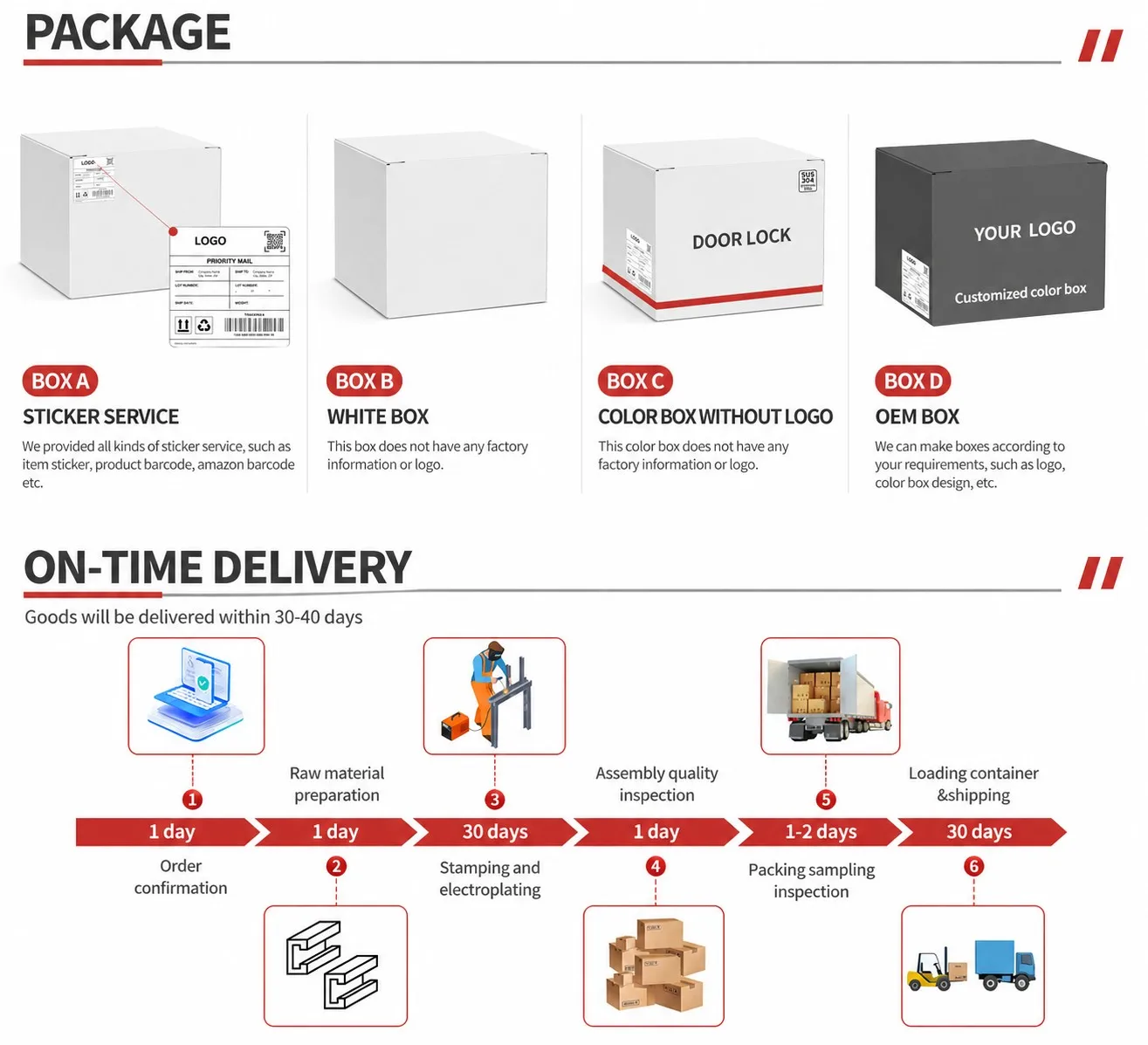


The K424 connector is supplied in die-cast zinc and, as K4241, in clear and ivory mouldings: a winged upright face with a fixing hole in each wing, a foot plate at a right angle to it, a gusset inside the angle and one central locking screw. Packed to count by material. Overall size, hole positions, screw size and the panel thickness range follow the issued drawing.
Send the material, the panel thickness and the screw you intend to use, and the connector can be checked against all three before anything ships. Where the corner has to carry a working load rather than only hold an angle, say so at enquiry and a steel bracket with a pressed rib is the connector to quote instead.


Comprehensive score